Follow me down the rabbit hole of Fuel PIMM repair.
#1
Bug  Follow me down the rabbit hole of Fuel PIMM repair.
Hi All,
I'm currently ordering more desoldering tweezers tip sizes to tackle a repair project given to me (graciously) by user noguri, related to this thread from a while back: https://forums.irixnet.org/thread-1170-p...l#pid13697

I've taken a fairly good once/twice over and I did try it in my Fuel and got both a immediate high voltage alert (like 6.28v on PIMM 5V line) but the start startup test was FILLED with cache issues too (which I didn't expect).  

Now according to my basic multimetering...it has at least one short , maybe TWO shorts, on it.  At first glance I think I see three different VRMs or voltage sources.  Two of theses either share a short or appear to be shorted.  This may explain the HIGH voltage instead of the lack of or low voltage (interaction of the two VRMs in short)?

It MAY be centered around the High Side of one of the VRM buck converters but these use a D-PAK (TO-252) designed FDD6612A (30V N-Channel Power MOSFET) (datasheet: https://www.digchip.com/datasheets/parts...2A-pdf.php) which I need to use desoldering tweezer paddles to remove without damage (intact) in case it's actually functional, but it's a great location to cause a circuit break to further find the short (I won't be simply using voltage injection this time, I'll try a current tracer first!).

Now I have no real proof that if the voltage was solved that cache issues would instantly resolve (the ICs may have been damaged and those are likely not solderable without a BGA machine...).  But I'm hoping that MAYBE the voltage issue caused some kind of trip mechanism (like a protection/clamping diode), to shunt the over-voltage, to protect the cache ICs so once proper voltage is restored...maybe they'll come back online.  

I'll be posting pictures when I do the removal work and isolation.  But I wanted to start the thread because basic checks sure say there's something wrong with these very templated/standard VRM circuits!

Follow me down the endless hole of trying to repair this puppy in a week or so.
weblacky
I play an SGI Doctor, on daytime TV.

Trade Count: (10)
Posts: 1,716
Threads: 88
Joined: Jan 2019
Location: Seattle, WA
Find Reply
11-18-2021, 07:40 AM
#2
RE: Follow me down the rabbit hole of Fuel PIMM repair.
Glad to help forensic medicine!
I'll stay tuned to see if dead can revive...

Onyx2 Rack Tezro Fuel Octane2 Octane2 Octane Indigo Indigo Indigo2 R10000/IMPACT Indy Indy Personaliris Visual Workstation 320 O2O2 + 1600SW
Noguri


Trade Count: (1)
Posts: 89
Threads: 12
Joined: Apr 2019
Location: Paris France
Find Reply
11-18-2021, 10:04 PM
#3
RE: Follow me down the rabbit hole of Fuel PIMM repair.
There's a really nice Conceptronic HGR 2000 Freedom Series SMT Repair BGA machine on ebay right now for US $995.00, if it wasn't that I'd have to drive to New Hampshire to pick it up I'd buy it today...

Project: Temporarily lost at sea
Plan: World domination! Or something...
vishnu
Tezro, Octane2, 2 x Onyx4

Trade Count: (0)
Posts: 1,245
Threads: 41
Joined: Dec 2017
Location: Minneapolis, Minnesota USA
Find Reply
11-19-2021, 01:49 AM
#4
RE: Follow me down the rabbit hole of Fuel PIMM repair.
Okay, I got to work on this more today.  I'm uncertain I've found THE ISSUE, hopefully I have.  I need to place an order soon for these parts anyway so I'll be doing that.

Okay, as I said before, this PIMM causes HIGH voltage on the PIMM 5V line = ~6.28v for me, which causes env shutdown.  It also showed a number of cache errors...I'm uncertain if it's directly related.  I probed around and thought there was a short between source and drain on a MSOFET rail and several decoupling caps...but had a very hard time proving it.

I used a current tracer from a ToneOhm 700...it kept pointing to a short on one of the sense resistors (F6F3) in the VRM region.
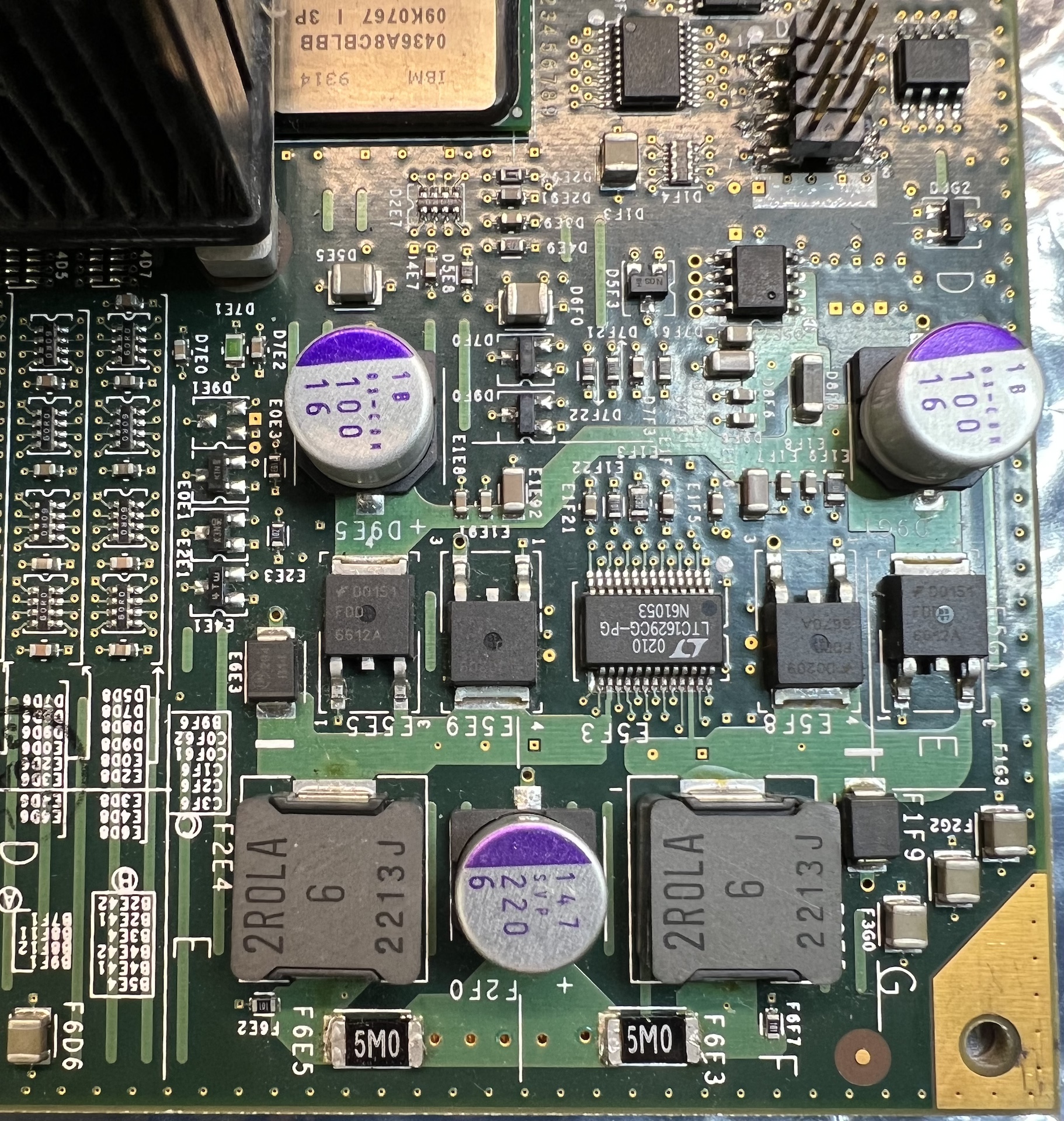
   

I used desoldering tweezers to remove them and retest the region...then it didn't really come up again.  I tested the sense resistors..they seem fine...so I put them back.  I then removed a MOSFET (E5G1) that claimed its drain and source were shorted in diode-mode testing (but 25 Ohms in ohm mode), It tested fine in my huntron outside the circuit, so I put that back too.

Not to be doo discouraged I re-examined the suggested application notes for these series of low-dropout regulators:
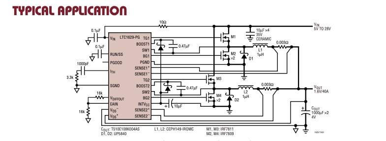
   

I originally thought that it may be the sense lines...as my huntron claimed the one of them (only for sense1+ I think) was shorted on the other side of a sense resistor.  But that wasn't really the case either...okay...lots of poor steps here and I was getting pretty demoralized.  The 220uF caps are registering WAY out of spec in circuit (using 300mV stimulus @ 1V, 30Hz) as something like 550uF-604uF (but that could be a connection issue in the in-circuit testing).  I'm going to have to test them out of circuit but even with tweezers, SMD caps don't really survive tweezers removal unhurt so I'll plan on just replacing all SMD electrolytic caps anyway.  But the huntron not only showed that the output cap (F2F0) was very HIGH ESR it also leaked...the other 220uF cap also leaked (leaking current, not leaking physical electrolyte!) but not as bad.  I'm not 100% sure so only replacement will prove that (by comparison).  

So I examined the circuit and saw that there are two diodes (schottky), these should be D1 and D2 on the usage diagram, they sit around the coils and the source on each MOSFET side and connect to the drains.  I thought, well if one of those were shorted that would possibly show as a diode-mode short from source to drain (unless a capacitor is in the way of my readings...which happens ALL THE TIME).

So I gently plucked the diodes (one at a time) from the board.  They are ONSEMI B14, and one of them (E6E3) was SHORTED (could only tell outside of circuit).  
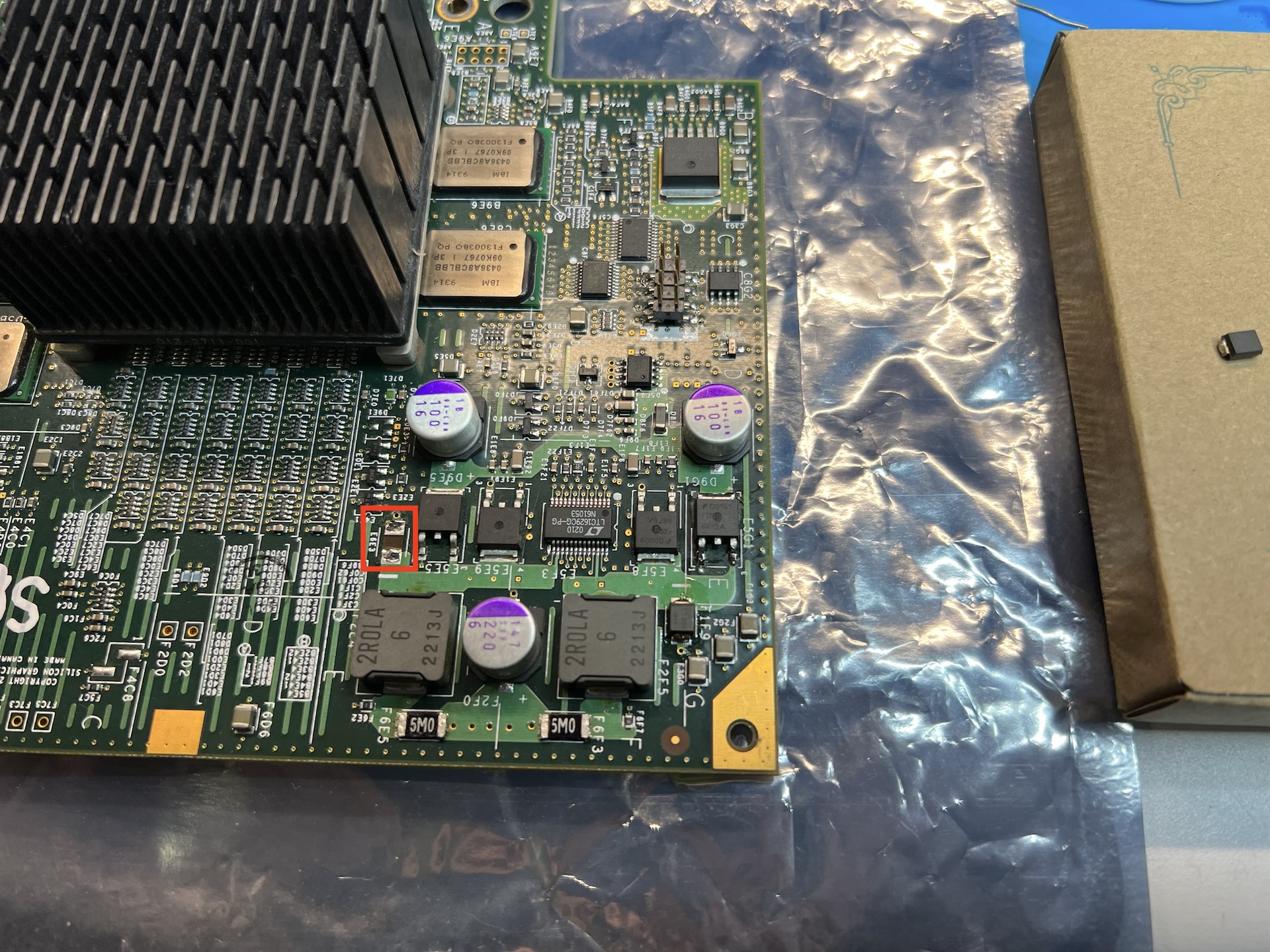
   

The bad thing is, even when you leave it out and place ONLY the good one back into position...you still hit the output cap during measurement so I never can tell it's shorted.  So once again, you have to remove components to even know but I knew there was some kind of short because I did try limited voltage injection 800mv @ 1A at the source/drain of the MOSFETs and it took, hard.  So I'm fairly sure I'm on the right track.

Now, reading the documentation for the chip it claims the function of these diodes (D1 & D2) is to ensure the gate clamps correctly and are not left on or signalled on via transients! So I guess back EMF suppression? So without this diode the paired MOSFET(s) would be ON more to nearly/maybe all the time.  However this would also clamp the voltage rail so I'm unsure why that would lead to an increase in PIMM 5V rail voltage...unless that's a symptom of being overdriven (overdrawn)?

Also, as I mentioned, the C-out Capacitor (220uF) is gone HIGH ESR, that very much affects the regulation of these circuits.

So, while not conclusive (there could be more bad things here...plus REAL damage given the CACHE errors) it is real damage, found.

At this stage I'm going to place an order for the SMD electrolytic caps, a couple new barrier diodes, and install them and see what happens.  I know my mainboard survives with this installed as-is so it should be okay with these changes.

Anyway, comments welcome...any additional eyes or thoughts on test/replacements.


Attached Files Image(s)
           
(This post was last modified: 11-23-2021, 11:51 PM by weblacky. Edit Reason: Spelling. )
weblacky
I play an SGI Doctor, on daytime TV.

Trade Count: (10)
Posts: 1,716
Threads: 88
Joined: Jan 2019
Location: Seattle, WA
Find Reply
11-23-2021, 06:48 AM
#5
RE: Follow me down the rabbit hole of Fuel PIMM repair.
I've placed orders for 2 x 220uF SVP, 3 x OS-CON 100uF, 4 x FDD6612A MOSFETs, and two new SMB sized barrier diodes (though I cannot find duplicates, hopefully they are improvements and not a problem source). Given that they are for dumping the reverse voltage spikes, I assume "similar" is good enough). I don't think I need these MOSFETs but something could happen so I threw them in anyway...It might be a good idea and change them anyway given the hard life they had with bad ESR and the shorted/clamped diode.
weblacky
I play an SGI Doctor, on daytime TV.

Trade Count: (10)
Posts: 1,716
Threads: 88
Joined: Jan 2019
Location: Seattle, WA
Find Reply
11-23-2021, 08:46 AM
#6
RE: Follow me down the rabbit hole of Fuel PIMM repair.
Okay...well that didn't go as planned.

I got the parts I thought I needed.  Removed all the old parts I thought where required (I didn't replace the MOSFETS because they looked okay, I still may have too).


Then cleaned and used low-temp solder paste to install the new stuff:
   

I thought things were good, installed it in my Fuel and..........

Instant ATTN 12V PIMM low at ~9.28v!!!!

Ugghh...so I 100% know the original error I saw was PIMM 5V too high at 6.28v...now there appears to be a short on the PIMM 12V line.  I'm very sure I didn't install parts backwards as I made a diagram for the caps and the diodes are marked on the board for orientation (and I felt that agreed with previous observations when I was last working on the diodes) and old pictures agree with what I have installed now.

So remember how I thought there might be multiple issues...well unless these parts were bad...there is still an issue.

Since I have everything apart right now, I'll try to use my working PIMM and compare this broken PIMM and see if I can find a safe way to locate the issue.


Also a note, I was wrong about the VRM output cap turning high ESR, it was showing as high ESR in circuit, but upon retesting it after removal it appears to be fairly normal.  So that was a false positive.  However, most of the 100uF caps were barely inside tolerance, so things needed changing anyway.

More to come.
(This post was last modified: 11-27-2021, 03:36 AM by weblacky. Edit Reason: Removing extra pic. )
weblacky
I play an SGI Doctor, on daytime TV.

Trade Count: (10)
Posts: 1,716
Threads: 88
Joined: Jan 2019
Location: Seattle, WA
Find Reply
11-27-2021, 03:34 AM
#7
RE: Follow me down the rabbit hole of Fuel PIMM repair.
Did you measure the actual voltage it complains about?

I'm facing a similar problem in my Challenge L deskside which was complaining about the -5 and -12 being out of spec. I measured them and they were fine, it was the monitoring circuit that was broken. Borrowed the system controller from my Onyx IR and all was good, installed a spare system controller and (1) that one complained that all voltages were 10% too low, but (2) the 5V supply which feeds the MCU on the system controller (which has 8 A/D channels used for measuring voltages and the blower) was 10% too high @ 5V6.

I'm now waiting for parts to rebuild the 5V supply on this system controller.
jan-jaap
SGI Collector

Trade Count: (0)
Posts: 1,048
Threads: 37
Joined: Jun 2018
Location: Netherlands
Website Find Reply
11-27-2021, 01:38 PM
#8
RE: Follow me down the rabbit hole of Fuel PIMM repair.
(11-27-2021, 01:38 PM)jan-jaap Wrote:  Did you measure the actual voltage it complains about?

I'm facing a similar problem in my Challenge L deskside which was complaining about the -5 and -12 being out of spec. I measured them and they were fine, it was the monitoring circuit that was broken. Borrowed the system controller from my Onyx IR and all was good, installed a spare system controller and (1) that one complained that all voltages were 10% too low, but (2) the 5V supply which feeds the MCU on the system controller (which has 8 A/D channels used for measuring voltages and the blower) was 10% too high @ 5V6.

I'm now waiting for parts to rebuild the 5V supply on this system controller.

Would you mind documenting what you did to repair the system controller? I suspect this could be the same thing going on with mine (though I haven't measured the voltages at the MCU, just at the regulators). Additionally, would you mind showing me where you measured the -5 and -12? I don't remember if I could find good test points for those.
Xav101
Challenge L

Trade Count: (0)
Posts: 41
Threads: 10
Joined: Aug 2019
Location: Ohio, USA
Find Reply
11-27-2021, 05:47 PM
#9
RE: Follow me down the rabbit hole of Fuel PIMM repair.
(11-27-2021, 01:38 PM)jan-jaap Wrote:  Did you measure the actual voltage it complains about?

I'm facing a similar problem in my Challenge L deskside which was complaining about the -5 and -12 being out of spec. I measured them and they were fine, it was the monitoring circuit that was broken. Borrowed the system controller from my Onyx IR and all was good, installed a spare system controller and (1) that one complained that all voltages were 10% too low, but (2) the 5V supply which feeds the MCU on the system controller (which has 8 A/D channels used for measuring voltages and the blower) was 10% too high @ 5V6.

I'm now waiting for parts to rebuild the 5V supply on this system controller.

In this case the answer is, no...I did not actually measure them...but that's because the DS1780 onboard the PIMM is what is reporting that for me (also tiny traces, live voltages...shaky hands...slipping...not a good plan). Everything comes through the MegArray and as you know...you don't mess with a MegArray!  So there are no obvious "tracks" for each voltage...I've just been guessing based on layout.  But as I mentioned, a lot of the PIMM rails show shorts in diode mode with 25 Ohms or less of resistance in Ohm mode.  They still pull current..but aren't a dead shorts.

It's very likely that there is a short BEHIND a ~25 Ohm resistance..so it pulls but the 25 Ohm resistance limits how much and saves the other regions. which also limits the severity of the voltage drop.

I truly believe it's accurate (at this time), however I am going to try to track down the 12V line by backtracking the 12V DS1780 sensor line on the PIMM.

Now when the DS1780 says the 12V rail is low...it doesn't mean the ENTIRE machine's 12V rail is low, only locally.

You see, if the V10 design is any indicator, the SGI designers loved using resistors and resistor arrays to current limit both sensors and various regions.  So we're often talking about a local voltage drop due to a local short.  Also these resistors compartmentalize the damage the short causes.

Also while it may be first-come-first-serve on the ATTN warnings, it's my impression (from at least a shorted V10 I had) that ALL errors are reported so I assume the PIMM 5V error was cured by the work I did, the fact that that larger feed 12V rail is also pulling down doesn't prevent the 5V PIMM line from working on standby as ~9V can still produce 5V via buck converter.

So this seems like a good and simple progress on finding multiple shorts.  But for now I'm trusting the DS1780 to do its job and let me know what's going on.

I know older machines don't have this luxury but with the knowledge of the DS1780 ICs exitance in this later platforms, we KNOW how voltages are reported and a general knowledge of which one reports what (only for PIMM and XIO at this time).  But, you make a good point...checking the protection around the PIMM DS1780 will also reveal the voltage tracks AND some if any of the protection resistors are out of tolerance that causing false errors.
weblacky
I play an SGI Doctor, on daytime TV.

Trade Count: (10)
Posts: 1,716
Threads: 88
Joined: Jan 2019
Location: Seattle, WA
Find Reply
11-28-2021, 12:47 AM
#10
RE: Follow me down the rabbit hole of Fuel PIMM repair.
(11-28-2021, 12:47 AM)weblacky Wrote:  
(11-27-2021, 01:38 PM)jan-jaap Wrote:  Did you measure the actual voltage it complains about?
[...]

In this case the answer is, no...I did not actually measure them...but that's because the DS1780 onboard the PIMM is what is reporting that for me

I have a O3K PIMM module where the DS1780 reports 3.2V while measuring showed 3.3V. Temperature is also off, which makes sense as everything is measured by the same ADC.

Challenge L Indy Indigo2 Indigo2 R10000/IMPACT O2 Octane Origin2000 Deskside Fuel Challenge S Origin 200 Origin 2000 Rack Origin 2000 Rack Origin 3200 Origin 350
fleedwood
O2

Trade Count: (0)
Posts: 24
Threads: 1
Joined: Dec 2020
Location: Germany
Find Reply
11-28-2021, 09:27 AM


Forum Jump:


Users browsing this thread: 2 Guest(s)