(03-20-2021, 01:46 PM)Trippynet Wrote: I think it depends to be honest! When I had issues with my Indigo2 PSU, I sent it to a firm here who re-capped it and sent it back. It continued to behave erratically, so I sent it back to them (their repair came with a 1-year warranty). They then found 4 resistors that weren't matching reference values so changed these and sent it back.
It was better after this, but still not perfect (lasts maybe 90 minutes then trips out). I tried sending it to them again, but they'd had enough so they declared the PSU as a write-off, refunded my money and returned the PSU to me. Disappointing, but on the plus side I have a re-capped supply and it has only cost me a few lots of postage, even if it is still flaky.
So my thoughts are, don't replace components if they aren't broken, but it's highly advisable to be able to stress-test the PSU you repair to make sure everything works. That was the problem with the firm I used - they could re-cap the PSU and test components, but they didn't have a way of actually running the PSU themselves to test it when it was live and under load.
Yes, I remember that. That’s a concern as always. I’m planning to ensure I have a spare junk system to do like days of on/idle with bouts of activity (like maybe network-based OS loads) to try to test a PSU in the intended system for several days (like 3?) straight.
But your scenario is the reason I don’t want to do “fix” jobs, because to be really sure, I need to put days of time into a PSU (including testing routines). That’s not a schedule I can keep. It’s easier to buy them, fix them, then do extended tests to feel confident about it.
Of course there is the issue of something being burnt out or wrong with an SGI, I don’t know if the older SGIs PSUs have good overcurrent protection or not. Another worry of mine, the new owner burns out the PSU with a bad mainboard and demands their money back.
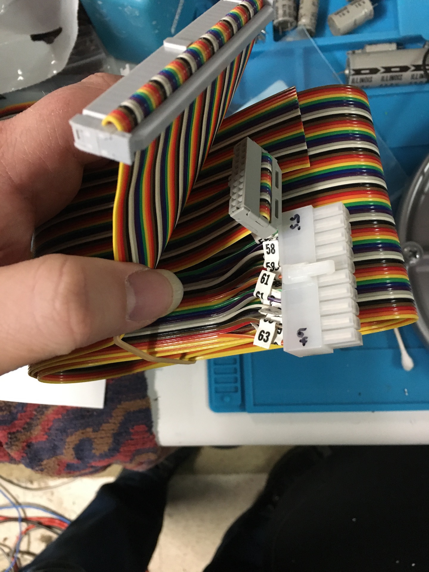
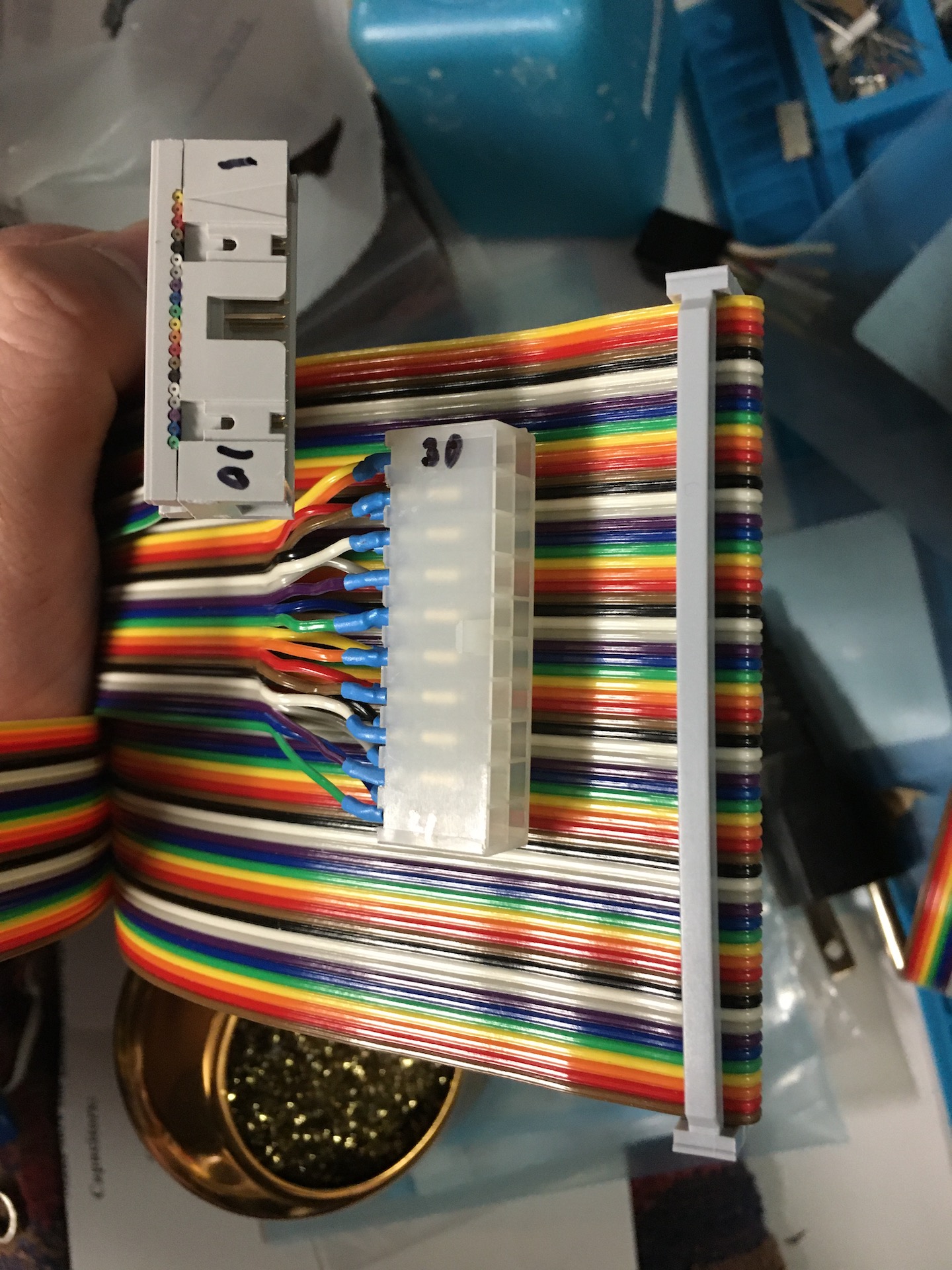
I’ve been trying to assemble odd test gear that I hope will give me an edge in finding issues. I’ve recently (of last week) finished my basic Indy PSU (to mainboard and to PSU) external interface cables for my curve tracer.


I’ve haven’t sat down and programmed a test routine yet, (that takes planning) so that still needs to be done to collect readings from all external connections. Then I need to plan out internal connections to test/probe using another harness. I’m not an EE so I only kind of understand the high-level stuff (hopefully). I’m more afraid of the large analog logic regions on the older boards. Not everything is ground-facing for easy probing. Nearly all the old PSUs have a separate daughter board that comes off the main board that carries the “smarts”. I think power-off testing will do the trick, but as to what and where to hook, I’m unsure at this time.
My hope would be a to get to a point where all ICs will just use test clips (have quite a few of those now) and test in-place and all resistor networks will have to be manually probed between neighboring IC or ground using common IC lead/ground and hand probes. I just need to find a way to hit all the big unique spots.
For the resistor networks, I may have to literally desolder each leg and do a massive individual test, unknown at this time.
There have been cheap overseas dc load testers appearing on eBay lately that eevblog claims are pretty good. They’re about ~$300 a piece for dual channel, 200w per channel, units. I’ve just put in an order for one ET5420 so at least I’ll have that for 5v and 3.3v loading while doing basic start testing.
I don’t have good info on bench testing PSUs, like ramp up current and sudden changes in current draw. But these units can do basic stuff like that without a computer program. I also don't own a really good oscilloscope, just a scope meter and a small uScope meter. Don't need one right now to justify the very high cost for the speed I'd need to actually use it for ripple. So we're sort of doing a lay-persons way right now, checking for AC V ripple being under 1% of DC V using a fluke multimeter.
I want to be sure, I know I’ll never be 100%, which worries me. But yeah, testing will be longer than soldering.
This dives into my pricing question because if it takes me 35-50 mins for soldering once you know what you’re doing. But the clean-up, alterations, and testing take longer.
One big thing with Indy PSUs is the logic daughter card is held on and to the case with glue (not fasteners). You have to break this glue to get it out…so I’ll have to redesign the interior to hold the PCB unless I want glue everything (which I don’t). I’m thinking of using some plastic PCB guides and attach a long one to the interior top of the case (with countersunk heads). So the new plastic rail stabilizes the daughter board once assembled and keeps it rigid.
Also as I mentioned in my above post, corrosion, most of these PSUs have corrosion and require new coatings, or galvanized zinc spraying, or plating. Given I’m not a photoshop expert and making vinyl labels isn’t my thing, I’m worried about producing the PSU labels if the cases needs that kind of work.
So yeah…lots of stuff…not just replacing 5 caps.


 NEED ->

 )
)